
3D gauging for forgings: measuring a hot, scaled, uneven part in seconds
Scale, draft and flash defeat a camera that measures outlines. Measuring height directly, with the datum taken from the part itself, is what makes a forged dimension hold its meaning shift after shift.
Omkaar Deshmane5 min read Updated 11 October 2026
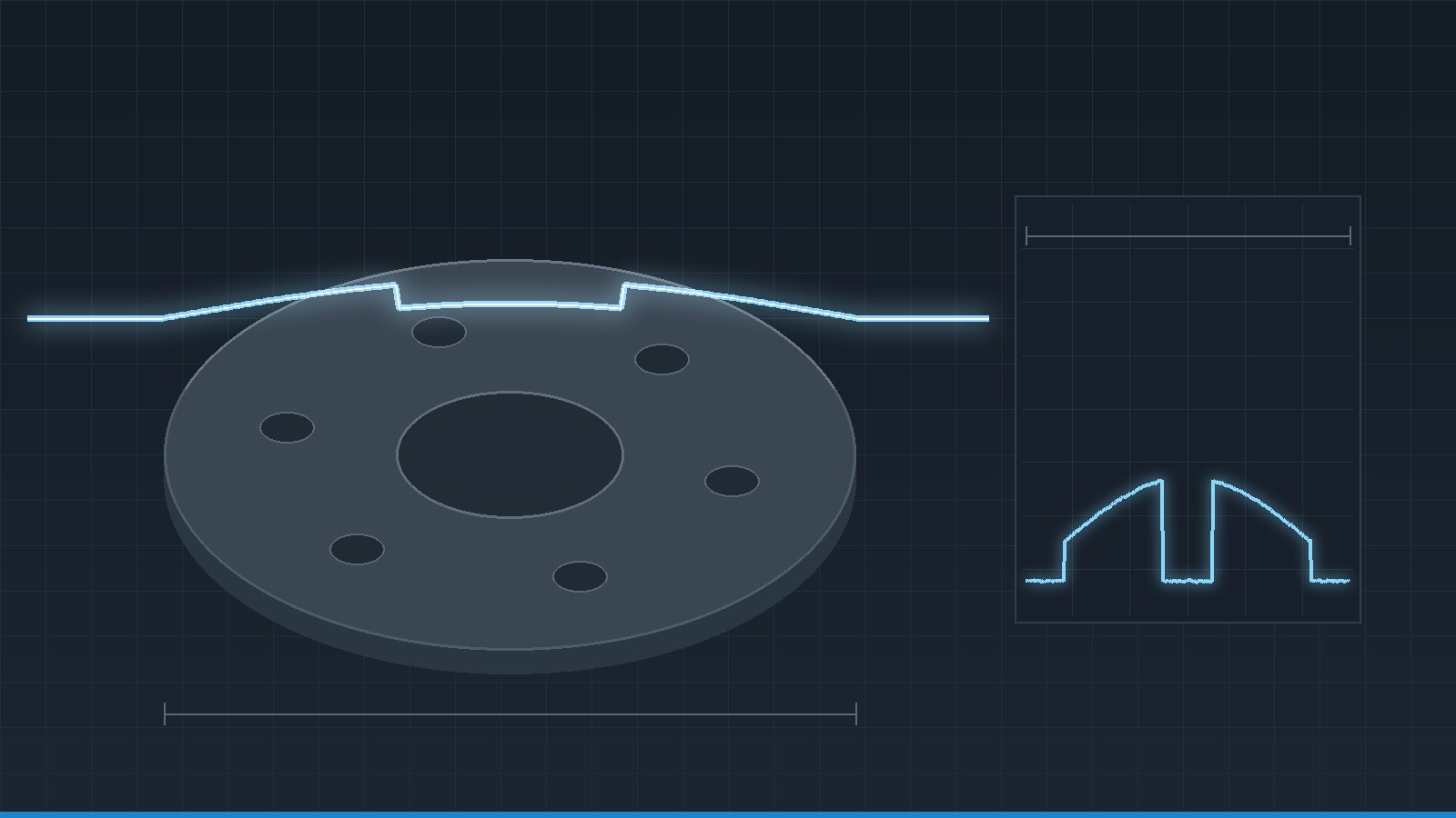
Forging gives you the shape cheaply. It also gives you scale, draft, flash, a surface whose colour changes from batch to batch, and a datum that quietly moved when the die wore. Then somebody asks for the outer diameter to within a tenth of a millimetre, on every piece, at twelve seconds a part.
That request is reasonable. It just cannot be answered by looking at the part's outline.
What is actually being measured
Before anyone talks about cameras, it is worth writing down the measurement list, because it decides everything after it. On forged and machined-from-forged components the list is usually some of these:
- Outer and inner diameter, at a stated height from the seating face, not "somewhere near the top".
- Pitch circle diameter and hole position, where holes are pierced rather than drilled.
- Height and step height between faces, which is where draft angle starts to matter.
- Flatness and runout of the seating face, often the quietest cause of downstream assembly trouble.
- Flash and under-fill at the die line: a height difference of a few tenths over a short distance.
- Bore depth and chamfer, where a profile is more honest than an edge.
Each of those is a distance in three dimensions. Some of them can be inferred from a silhouette if the part is perfectly presented, perfectly lit and perfectly repeatable in colour. Forgings are none of those things.
Why a camera on its own struggles
A 2D camera measures contrast. On a forging, contrast moves for reasons that have nothing to do with the dimension:
| What changes | What the camera sees | What it does to the reading |
|---|---|---|
| Scale and oxide colour | A darker or softer edge | The edge shifts by a pixel or two, part to part |
| Draft angle | A sloped wall lit unevenly | The diameter is read at an unknown height |
| Flash at the die line | An extra bright line | A false outer edge, or a false reject |
| Part rocking on an uneven face | A tilted silhouette | Length and diameter both drift |
| Shot blast finish between batches | Changed reflectance | The threshold that worked last month no longer does |
You can fight all of this with better lighting and tighter fixturing, and for a flat machined part that is exactly the right answer. On a forging it becomes a maintenance job that never ends. A production engineer should not have to re-teach a threshold because the blast media was changed.
What goes on the line instead
The approach that holds up is to measure height directly rather than infer it from contrast. In practice that means a blue laser line profiler, moved across the part on a single axis or carried by a robot, with the part on a simple located nest rather than a precision fixture.
- Blue laser rather than red. On hot, scaled and dark surfaces the shorter wavelength scatters less
into the sensor and gives a cleaner profile. On bright machined faces it also reduces the speckle that blurs a red line.
- A profile, not an image. Each scan line is a set of real height points in millimetres. Scale that
changes the surface's colour hardly changes its height, so the reading stops drifting with the batch.
- Datum built from the part, not the fixture. The seating face is fitted as a plane from the scan, and
every height and diameter is reported from that plane. The part can sit a degree out and the numbers do not move.
- Features fitted, not thresholded. A diameter comes from a circle fitted through hundreds of points
on the wall at the stated height, so a single bad point cannot decide the verdict.
- Flash measured as what it is. A height difference along the die line, with its own tolerance,
separate from the diameter.
The useful change is not the sensor. It is that the number on the screen now has the same meaning on Monday as it had on Friday.
Hot parts, and the part nobody mentions
If the part is measured warm, every dimension is larger than it will be in the gauge room, and by an amount that depends on where in the cooling curve it was caught. There are two honest ways to deal with this, and one dishonest one.
- Measure cold, after a known dwell. Simplest, and what we recommend whenever the line layout allows
it. The measurement then matches the inspection report without argument.
- Measure warm and correct for it, with the part's temperature measured at the same time and a
coefficient agreed in writing. This works, but the correction has to be part of the record, not hidden in the system.
- Measure warm and ignore it. This is the one that produces a system everybody stops believing
within a month.
Proving it before anyone trusts it
A measurement system earns its place by a study, not by a demonstration. What we run before handover:
- Repeatability on one part. The same piece, loaded and unloaded thirty times, to separate the
sensor's noise from the loading. If repeatability is not comfortably inside a tenth of the tolerance band, nothing else matters yet.
- Reproducibility across operators and shifts, because the nest is loaded by hand in most cells.
- Bias against a reference. A set of parts measured on a CMM or a calibrated gauge, then on the
system, with the difference plotted rather than averaged away. A constant offset is easy to live with. A sloping one tells you the datum is wrong.
- A deliberate reject set. Parts machined or selected outside tolerance, to prove the system catches
what it is there to catch. A system that has never said "no" has not been tested.
We report all of it as a document with the raw figures attached, not as a pass mark.
Where the twelve seconds go
A useful rule of thumb for a single-axis scan cell, on a part the size of a hub or a flange:
| Step | Typical |
|---|---|
| Load and clamp in a located nest | 2 to 3 s |
| Scan pass, one axis | 2 to 4 s |
| Fitting, measurement and verdict | under 1 s |
| Unload and sort | 2 to 3 s |
The scan is rarely the bottleneck. Loading is. That is why the first question we ask about cycle time is how the part arrives, not how fast the sensor runs.
What to send us if this is your problem
A feasibility answer takes a few days if we have the right things to work with:
- Two or three real parts, including at least one you would reject, and the reason you reject it.
- The drawing with the dimensions that matter marked, each with its tolerance and its datum.
- The cycle time available, and whether the part arrives on a conveyor, in a bin or in a tray.
- Whether the part is warm at the measuring station, and roughly how warm.
- What has to happen when the answer is "no" — divert, mark, stop the line, or simply record it.
We will tell you what is measurable, to what repeatability, and what it takes to keep it measurable every shift. If a 2D camera and good lighting will do the job, we will say that too; it is the cheaper system to own.